Network Documentation
Network documentation is a collection of records documenting a network’s hardware, software, and configurations.
Physical Network Diagrams
A physical network diagram is a graphical representation of a network’s physical topology.
Logical Network Diagrams
A logical network diagram is text-based documentation used to record a network’s logical topology
Kinds
- A baseline configuration is a node’s initial configuration at time of deployment.
- A standard naming convention is the use of a consistent naming scheme, or convention, for computing resources.
- An IP schema is the use of a consistent IP addressing plan, or schema, for network resources.
Schematics
A schematic is a simplified or abstracted representation of a system.
- can show the general placement of equipment and telecommunications rooms, plus device and port IDs, without trying to capture the exact position or relative size
- can be used to represent the logical structure of the network in terms of zones and subnets
Making Network Schematics
- do not represent too much information in a single diagram
- e.g., create separate diagrams for PHY, Data Link, and Logical (IP) layers
- information for each layer:
- Physical layer
- asset IDs, cable links, wall/patch panel/switch port IDs
- use color coding or line styles to represent cable type
- Data Link layer
- shows interconnections between switch and routers
- with asset IDs, interface IDs, and link-layer protocol and bandwidth
- use line thickness to represent bandwidth
- use labels as well for clarity
- shows interconnections between switch and routers
- Logical (IP) layer
- IP addresses of router interfaces, firewalls
- links showing the IP network ID and netmask, VLAN ID, and DHCP scope
- Application layer
- server instances and TCP/UDP ports in use
- configuration information and performance baselines (CPU, memory, storage, network utilization)
- Physical layer
- can be drawn manually, using tools, or compiled automatically from network mapping software
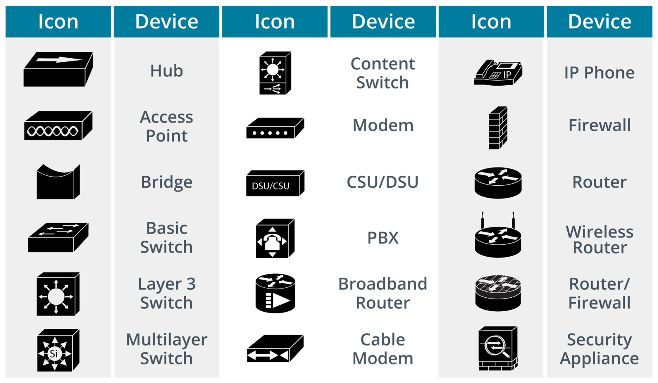
- can use representative icons or drawings of actual product models
- Cisco icons are standard: