Variable Length Subnet Mask (VLSM)
- IPv4 address space is close to being exhausted
- makes it difficult for ISPs to allocate public addresses
- to mitigate this, supernetting is used
- simplifies the information Internet routers need to locate IP networks
- variable length subnet mask (VLSM) allows a network designer to allocate ranges of IP address to subnets that match the predicted need for numbers of subnets and hosts per subnet more closely
- compliments supernetting
- without VLSM, have to allocate subnetted ranges of addresses that are the same size and use the same subnet mask throughout the network
- means that
- some subnets have many wasted IP addresses
- or additional routing interfaces must be installed to connect several smaller subnets together within a single building or department
- means that
- VLSM allows different length netmasks to be used within the same IP network
- allows more flexibility in the design process
Example
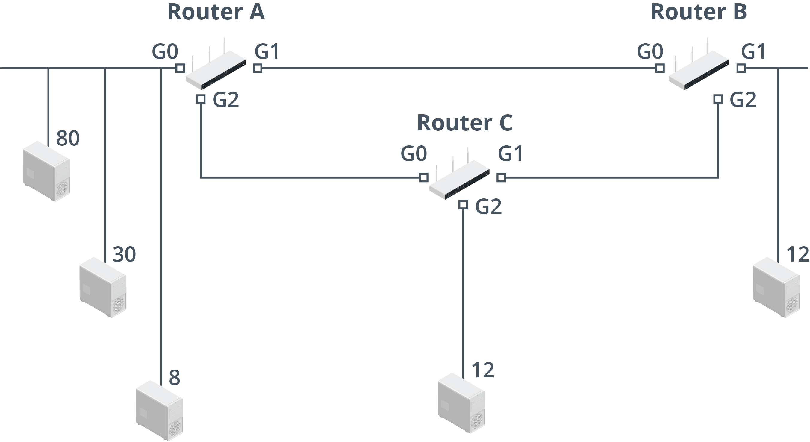
Consider a company with three sites
- each with differing network sizes and IP address requirements
- have subnets representing point-to-point WAN link between the routers
- VLSM design proceeds by:
- identifying the subnets with the most hosts
- organizing the scheme in descending order
- remember that each power of 2 is double the previous one:
4 8 16 32 64 128 256
- largest requirement is for 80 hosts
= 64 max values - not enough so next nearest match is
- need 7 bits for host addressing
- allows for 126 host addresses (
) - prefix = /25 (
)
- next requirement is met by a 5-bit host address space
- allows for exactly 30 addresses, no room for growth
- using 6 bits is safer, but we will use the closest match instead (/27)
- next three requirements are for 8, 12, and 12 hosts
- all require 4 bits
- gives 14 usable addresses
- routers use point-to-point links, so no more than two addresses will be required
- can be met by selecting a /30 prefix
Final VLSM design:
|Office/Subnet|Required Number of IP Addresses|Mask Bits|Actual Number of IP Addresses|Prefix|
|---|---|---|---|---|
|Main Office 1 (Router A)|80|7|126|/25|
|Main Office 2 (Router A)|30|5|30|/27|
|Main Office 3 (Router A)|8|4|14|/28|
|Branch Office (Router B)|12|4|14|/28|
|Branch Office (Router C)|12|4|14|/28|
|Router A – Router B|2|2|2|/30|
|Router A – Router C|2|2|2|/30|
|Router B – Router C|2|2|2|/30|
- all subnets except for Main Office 2 have room for growth
- analyzing the final design, we find that there are 36 unused addresses at the end of the range
- so would have been space to use a /26 prefix for the group of 30 hosts
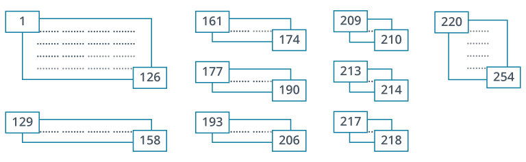
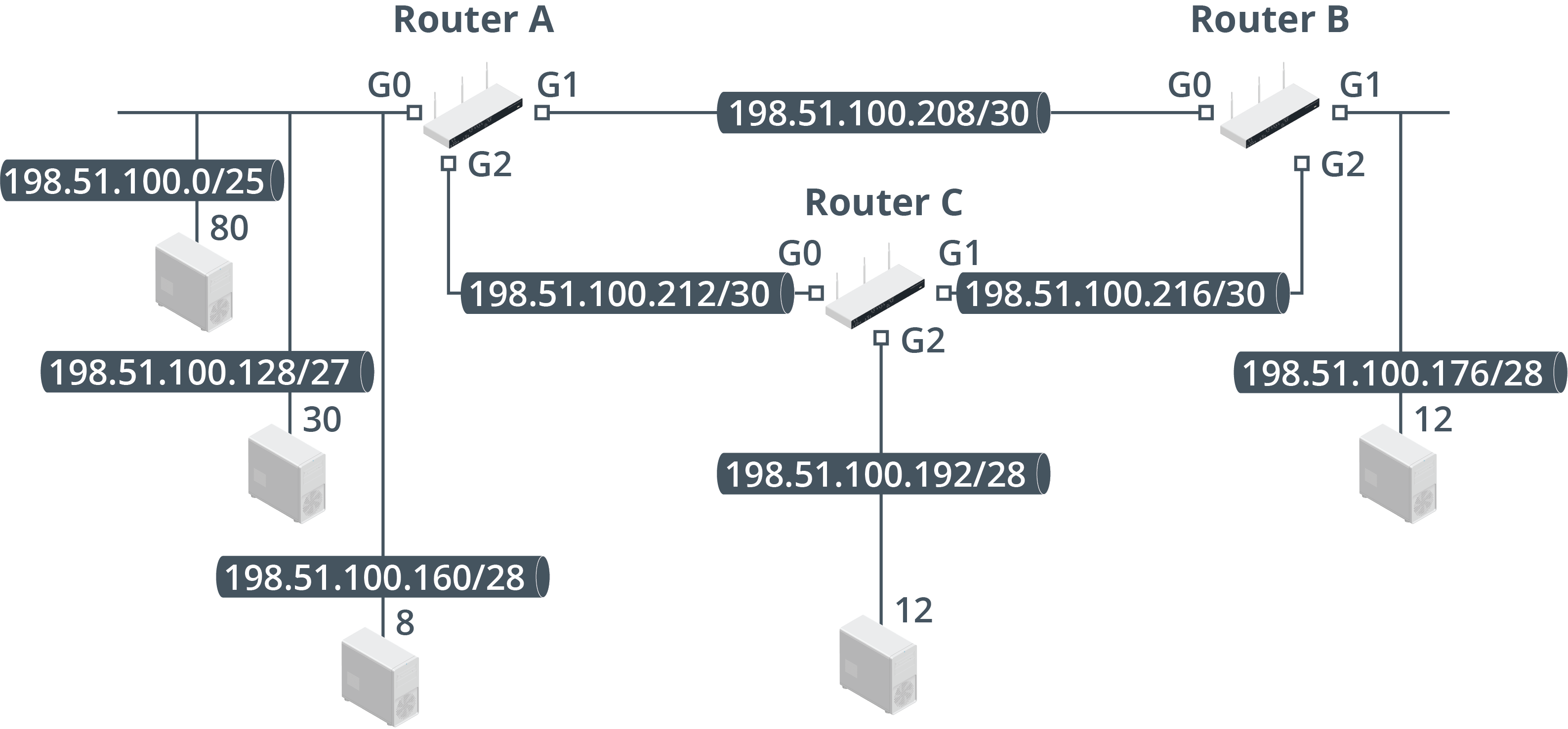
IP address ranges generated by the VLSM design:
|Office|Subnet|Subnet Mask|Useable Host Address Range|Broadcast Address|
|---|---|---|---|---|
|Main Office 1 (Router A)|198.51.100.0/25|255.255.255.128|1—126|127|
|Main Office 2 (Router A)|198.51.100.128/27|255.255.255.224|129—158|159|
|Main Office 3 (Router A)|198.51.100.160/28|255.255.255.240|161—174|175|
|Branch Office (Router B)|198.51.100.176/28|255.255.255.240|177—190|191|
|Branch Office (Router C)|198.51.100.192/28|255.255.255.240|193—206|207|
|Router A – Router B|198.51.100.208/30|255.255.255.252|209—210|211|
|Router A – Router C|198.51.100.212/30|255.255.255.252|213—214|215|
|Router B – Router C|198.51.100.216/30|255.255.255.252|217—218|219|VLSM network topology summarized below: