Structured Cabling System
A structured cabling scheme is a standard way of provisioning cabled networking for computers in an office building.
- known as ANSI/TIA/EIA 568 Commercial Building Telecommunications Wiring Standard
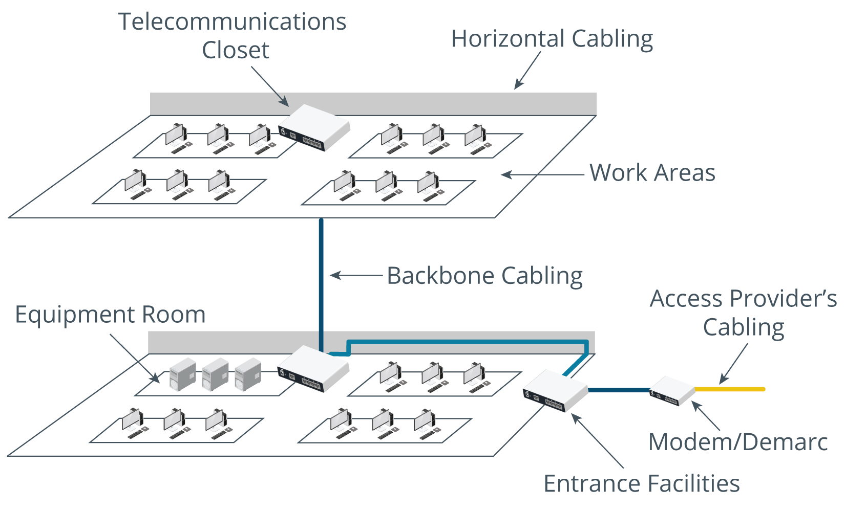
- locations and subsystems within a structured cabling system:
- Work area — space where user equipment is located and connected to the network
- usually via a patch cable plugged into a wall port
- Horizontal cabling — connects user work areas to an intermediate distribution frame (IDF)
- IDF is a passive wiring panel providing a central termination point for cabling
- consists of cabling for a single floor
- when using copper cabling, IDF must be within 90 m (295 ft) cabling distance of each wall port
- multiple IDFs on same floor are linked by horizontal cross connects
- Telecommunications room — houses an intermediate distribution frame and networking equipment
- is a termination point for the horizontal cabling along with a connection to backbone cabling
- must be used only for networking equipment, not general storage
- should be secured by lock
- Backbone cabling — Connects IDFs to a main distribution frame (MDF)
- MDF is a passive wiring panel providing a central termination point for cabling
- distributes backbone wiring through a building and connections to external access provider networks
- referred to as vertical cabling
- MDF is a passive wiring panel providing a central termination point for cabling
- Entrance facilities/demarc — telecommunications room marking the point at which external cabling is joined to internal cabling via MDF
- required:
- to join the local exchange carrier’s (LEC) network
- for inter-building communications
- demarcation point is where the access provider’s network terminates and the organization’s network begins
- required:
- Work area — space where user equipment is located and connected to the network
Info
- Smaller facilities may not require an IDF
- Wall ports can be terminated to a single MDF if distance limits are not exceeded.