Fiber Optic Installation
- can be installed in the same topology as copper cable using distribution frames and switches
- long-distance cables are laid as trunks or rings with repeaters or amplifiers to strengthen signal
- duplex fiber is installed in pairs of strands
- one strand for transmit (Tx)
- one strand for receive (Rx)
- Fiber optic connectors are quite easy to damage and should not be repeatedly plugged in and unplugged
- Unused ports and connectors should be covered by a dust cap to minimize the risk of contamination
Fiber Optic Patch Cords
- can come with same connector on each end or a mix of connectors
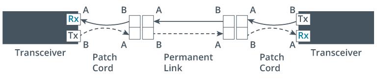
- duplex patch cords must maintain the correct polarity
- Tx port on transmitter is linked to the Rx port on the receiver and vice versa
- TIA/EIA standard sets out a system of A to B polarity
- each element in the link must perform a crossover
- must be an odd number of elements
- E.g., two patch cords and a permanent link (3 elements)
- connectors are keyed to prevent incorrect insertion
- can use an optical power meter to determine whether an optical signal is being received from a particular fiber
Finishing Type
- core of a fiber optic connector is a ceramic or plastic ferrule that holds the glass strand and ensures continuous reception of the light signals
- tip of ferrule can be finished in several formats:
- Physical Contact (PC)
- common choice for standard fiber optic applications
- Ultra Physical Contact (UPC)
- faces of the connector and fiber tip are polished so that they curve slightly and fit together better
- has high-quality polish
- significantly reduces back reflection compared to PC
- crucial for high data transmission quality
- ensures light signals are transmitted with greater clarity and strength
- suitable for applications that demand high performance and reliability
- e.g., high performance office building network
- Angled Physical Contact (APC)
- faces are angled for an even tighter connection
- angled polish provides greatest reduction in back reflection
- typically used in applications that are highly sensitive to back reflections
- e.g., long-distance and high-bandwidth transmissions
- more expensive than UPC,
- cannot be mixed with PC or UPC
- must match finishing type when choosing a connector type
- APC finishing is not often supported by patch panels, transceivers, or switch ports designed for Ethernet
- cable jacket and connector color-coding conventions:
| Type | Jacket Color | Connector Color |
|---|
| OM1 | Orange | Beige |
| OM2 | Orange | Black |
| OM3/OM4 | Aqua | Aqua |
| SMF PC/UPC | Yellow | Blue |
| SMF APC | Yellow | Green |