Copper Cabling Test Tools
- Once you have terminated cable, you must test it to ensure that each wire makes good electrical contact and is in the correct pin position
- best time to verify wiring installation and termination is just after you have made all the connections
- you should still have access to the cable runs
- Identifying and correcting errors at this point will be much simpler than when you are trying to set up end user devices
Cable Tester
A cable tester reports detailed information on the physical and electrical properties of the cable.
- pair of devices designed to attach to each end of a cable
- It can be used to test:
- a patch cord
- can be connected via patch cords to a wall port and patch panel port to test the permanent link
- The tester energizes each wire in turn, with an LED indicating successful termination
- If an LED does not activate
- the wire is not conducting a signal, typically because the insulation is damaged or the wire isn’t properly inserted into the plug or IDC
- If the LEDs do not activate in the same sequence at each end
- the wires have been terminated to different pins at each end
- Use the same type of termination on both ends
- tests and reports:
- cable conditions
- crosstalk
- attenuation
- noise
- resistance
- certifiers can test and certify a cable’s performance category
Wire Map Testers
- a wire map tester device can detect improper termination issues
- to perform a wire map test:
- base unit is connected to one end of the cable and a remote unit to the other
- test is activated, an LED for each wire conductor lights up in sequence
- If an LED fails to light or does not light in sequence,
- there is a problem with the cable and/or termination
- can identify the following problems:
- continuity (open) — conductor does not form a circuit because of cable damage or the connector is not properly wired
- short — two conductors are joined at some point, because the insulating wire is damaged, or a connector is poorly wired
- incorrect pin-out/incorrect termination/mismatched standards
- conductors are incorrectly wired into the terminals at one or both ends of the cable
- common transpositions:
- reversed pair — conductors in a pair have been wired to different terminals
- e.g., pin 3 to pin 6, etc
- crossed pair (TX/RX transposed — conductors from one pair have been connected to pins belonging to a different pair
- e.g., pins 3 and 6 to pins 1 and 2
- may be done deliberately to create a cross-over cable
- would not be used to link a host to switch
- reversed pair — conductors in a pair have been wired to different terminals
- split pair — both ends of a single wire in one pair are wired to terminals belonging to a different pair
- only detected by a cable tester that measures crosstalk
- to perform a wire map test:
Tone Generator and Toner Probe
- Many cable testers also incorporate the function of a toner probe
- a tone generator (toner) and probe are used to trace a cable from one end to the other
- used to identify a cable from within a bundle
- when the cables have not been labeled properly
- aka fox and hound
- The tone generator is connected to the cable using an RJ45 jack
- applies a continuous audio signal on the cable
- probe is used to detect the signal and follow the cable over ceilings and through ducts or identify it from within the rest of the bundle
- used to identify a cable from within a bundle
- Disconnect the other end of the cable from any network equipment before activating the tone generator
Loopback Plug
- A loopback plug is used to test a NIC or switch port
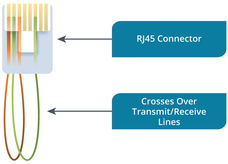
- can make a basic loopback plug from a 6” cable stub where the wires connect pin 1 to pin 3 and pin 2 to pin 6
- When you connect a loopback plug to a port, you should see a solid link LED showing that the port can send and receive
Info
A loopback plug made from a cable stub is unlikely to work with Gigabit Ethernet ports. You can obtain manufactured Gigabit port loopback testers.