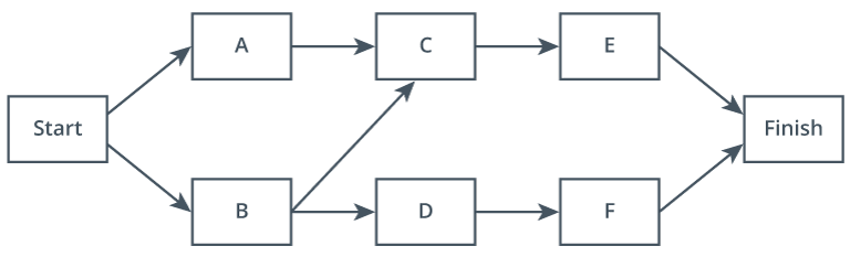
Precedence Diagram Method (PDM)
Precedence diagram method (PDM) is a project schedule network diagramming method that uses rectangular or circular nodes to represent activities and arrows to represent precedence relationships between activities.
- use rectangles and arrows to show the dependencies between activities
- useful for visualizing activities and dependencies
- diagram layout describes the flow of work
- A “Start” rectangle on the left side of the diagram represents the start of a project
- a “Finish” rectangle on the right side represents the end
- project activities are arranged in a sequential flow from left to right
- left side of the activity rectangle is the start of the activity, and the right is the finish
- An arrow connects the two activity rectangles if activities depend on one another
- dependency type is depicted in one of two ways:
- use the connection points to describe the relationships
- e.g., SF dependency would draw an arrow from the left side of the first activity to the right side of the second activity
- connect the shapes from end to end and label each arrow with the relationship type (FS, FF, SS, SF)
- use the connection points to describe the relationships